http://www.youtube.com/watch?v=ywz7vN0GF_Y
Para el proyecto final de la clase me gustaría realizar un "cubo musical".
Sería un dispositivo de madera posiblemente (u otro material) con forma de cubo, y en cada cara tendrá un sensor que accionara un sonido. La idea es que al tomar el cubo y tocar las caras de este conforme una melodía.
Decidí hacer este proyecto como una continuación del primer proyecto que construí para mi examen de Tecnologías Aplicadas, el cual consistía en unos dispositivos que actuaban como teclas y al apretar cada una sonaba un pedazo de una canción. Mi objetivo es llevar esta idea a una nueva versión, construir un dispositivo mas formal y si es posible añadir nuevos elementos.
Quiero realizar este proyecto para poder aprender más sobre los sensores de presión u otros componentes de arduino.
La melodía que resulte de este cubo busca crear una atmósfera de reflexión, admiración y calma como la que se forma con los cantos gregorianos de la época medieval.
Aquí se puede escuchar unos ejemplos:
*Como hacer el proyecto:
Yo creo que para realizar este proyecto debería establecer una conexión entre Arduino y MaxMSP. Realice un ejercicio en el cual conecte dos sensores (los que tenía) un potenciómetro lineal y un sensor flex a MaxMSP y al activar los sensores estos intervinieran una onda de sonido que la controlaba el programa MaxMSP.
Para realizar esto cargue el código StandardFirmata en Arduino y conecte los sensores. Luego con Maxuino hice la conexión entre los sensores de MaxMSP.
*Como conectar los sensores:
-Potenciómetro: conectar un cable desde 5v hasta la pata izquierda del sensor. Conectar un cable desde GND hasta la pata derecha del sensor. Conectar un cable desde A2 hasta la pata central del sensor.
-Sensor flex: conectar un cable desde 5v hasta la pata derecha del sensor. Conectar un cable desde GND a la linea azul del breadboard, conectar una resistencia desde la linea azul hasta la linea H. Conectar un cable desde un extremo de la resistencia hasta el A0 y conectar un cable al lado del cable de A0 hasta la pata izquierda del sensor.


*Programa MaxMSP y conexiones con Arduino:

Se puede encontrar en Exmaple, Firmata, StandardFirmata
/*
Copyright (C) 2006-2008 Hans-Christoph Steiner. All rights reserved.
This library is free software; you can redistribute it and/or
modify it under the terms of the GNU Lesser General Public
License as published by the Free Software Foundation; either
version 2.1 of the License, or (at your option) any later version.
See file LICENSE.txt for further informations on licensing terms.
formatted using the GNU C formatting and indenting
*/
/*
* TODO: use Program Control to load stored profiles from EEPROM
*/
#include <Servo.h>
#include <Firmata.h>
/*==============================================================================
* GLOBAL VARIABLES
*============================================================================*/
/* analog inputs */
int analogInputsToReport = 0; // bitwise array to store pin reporting
/* digital input ports */
byte reportPINs[TOTAL_PORTS]; // 1 = report this port, 0 = silence
byte previousPINs[TOTAL_PORTS]; // previous 8 bits sent
/* pins configuration */
byte pinConfig[TOTAL_PINS]; // configuration of every pin
byte portConfigInputs[TOTAL_PORTS]; // each bit: 1 = pin in INPUT, 0 = anything else
int pinState[TOTAL_PINS]; // any value that has been written
/* timer variables */
unsigned long currentMillis; // store the current value from millis()
unsigned long previousMillis; // for comparison with currentMillis
int samplingInterval = 19; // how often to run the main loop (in ms)
Servo servos[MAX_SERVOS];
/*==============================================================================
* FUNCTIONS
*============================================================================*/
void outputPort(byte portNumber, byte portValue, byte forceSend)
{
// pins not configured as INPUT are cleared to zeros
portValue = portValue & portConfigInputs[portNumber];
// only send if the value is different than previously sent
if(forceSend || previousPINs[portNumber] != portValue) {
Firmata.sendDigitalPort(portNumber, portValue);
previousPINs[portNumber] = portValue;
}
}
/* -----------------------------------------------------------------------------
* check all the active digital inputs for change of state, then add any events
* to the Serial output queue using Serial.print() */
void checkDigitalInputs(void)
{
/* Using non-looping code allows constants to be given to readPort().
* The compiler will apply substantial optimizations if the inputs
* to readPort() are compile-time constants. */
if (TOTAL_PORTS > 0 && reportPINs[0]) outputPort(0, readPort(0, portConfigInputs[0]), false);
if (TOTAL_PORTS > 1 && reportPINs[1]) outputPort(1, readPort(1, portConfigInputs[1]), false);
if (TOTAL_PORTS > 2 && reportPINs[2]) outputPort(2, readPort(2, portConfigInputs[2]), false);
if (TOTAL_PORTS > 3 && reportPINs[3]) outputPort(3, readPort(3, portConfigInputs[3]), false);
if (TOTAL_PORTS > 4 && reportPINs[4]) outputPort(4, readPort(4, portConfigInputs[4]), false);
if (TOTAL_PORTS > 5 && reportPINs[5]) outputPort(5, readPort(5, portConfigInputs[5]), false);
if (TOTAL_PORTS > 6 && reportPINs[6]) outputPort(6, readPort(6, portConfigInputs[6]), false);
if (TOTAL_PORTS > 7 && reportPINs[7]) outputPort(7, readPort(7, portConfigInputs[7]), false);
if (TOTAL_PORTS > 8 && reportPINs[8]) outputPort(8, readPort(8, portConfigInputs[8]), false);
if (TOTAL_PORTS > 9 && reportPINs[9]) outputPort(9, readPort(9, portConfigInputs[9]), false);
if (TOTAL_PORTS > 10 && reportPINs[10]) outputPort(10, readPort(10, portConfigInputs[10]), false);
if (TOTAL_PORTS > 11 && reportPINs[11]) outputPort(11, readPort(11, portConfigInputs[11]), false);
if (TOTAL_PORTS > 12 && reportPINs[12]) outputPort(12, readPort(12, portConfigInputs[12]), false);
if (TOTAL_PORTS > 13 && reportPINs[13]) outputPort(13, readPort(13, portConfigInputs[13]), false);
if (TOTAL_PORTS > 14 && reportPINs[14]) outputPort(14, readPort(14, portConfigInputs[14]), false);
if (TOTAL_PORTS > 15 && reportPINs[15]) outputPort(15, readPort(15, portConfigInputs[15]), false);
}
// -----------------------------------------------------------------------------
/* sets the pin mode to the correct state and sets the relevant bits in the
* two bit-arrays that track Digital I/O and PWM status
*/
void setPinModeCallback(byte pin, int mode)
{
if (IS_PIN_SERVO(pin) && mode != SERVO && servos[PIN_TO_SERVO(pin)].attached()) {
servos[PIN_TO_SERVO(pin)].detach();
}
if (IS_PIN_ANALOG(pin)) {
reportAnalogCallback(PIN_TO_ANALOG(pin), mode == ANALOG ? 1 : 0); // turn on/off reporting
}
if (IS_PIN_DIGITAL(pin)) {
if (mode == INPUT) {
portConfigInputs[pin/8] |= (1 << (pin & 7));
} else {
portConfigInputs[pin/8] &= ~(1 << (pin & 7));
}
}
pinState[pin] = 0;
switch(mode) {
case ANALOG:
if (IS_PIN_ANALOG(pin)) {
if (IS_PIN_DIGITAL(pin)) {
pinMode(PIN_TO_DIGITAL(pin), INPUT); // disable output driver
digitalWrite(PIN_TO_DIGITAL(pin), LOW); // disable internal pull-ups
}
pinConfig[pin] = ANALOG;
}
break;
case INPUT:
if (IS_PIN_DIGITAL(pin)) {
pinMode(PIN_TO_DIGITAL(pin), INPUT); // disable output driver
digitalWrite(PIN_TO_DIGITAL(pin), LOW); // disable internal pull-ups
pinConfig[pin] = INPUT;
}
break;
case OUTPUT:
if (IS_PIN_DIGITAL(pin)) {
digitalWrite(PIN_TO_DIGITAL(pin), LOW); // disable PWM
pinMode(PIN_TO_DIGITAL(pin), OUTPUT);
pinConfig[pin] = OUTPUT;
}
break;
case PWM:
if (IS_PIN_PWM(pin)) {
pinMode(PIN_TO_PWM(pin), OUTPUT);
analogWrite(PIN_TO_PWM(pin), 0);
pinConfig[pin] = PWM;
}
break;
case SERVO:
if (IS_PIN_SERVO(pin)) {
pinConfig[pin] = SERVO;
if (!servos[PIN_TO_SERVO(pin)].attached()) {
servos[PIN_TO_SERVO(pin)].attach(PIN_TO_DIGITAL(pin));
} else {
Firmata.sendString("Servo only on pins from 2 to 13");
}
}
break;
case I2C:
pinConfig[pin] = mode;
Firmata.sendString("I2C mode not yet supported");
break;
default:
Firmata.sendString("Unknown pin mode"); // TODO: put error msgs in EEPROM
}
// TODO: save status to EEPROM here, if changed
}
void analogWriteCallback(byte pin, int value)
{
if (pin < TOTAL_PINS) {
switch(pinConfig[pin]) {
case SERVO:
if (IS_PIN_SERVO(pin))
servos[PIN_TO_SERVO(pin)].write(value);
pinState[pin] = value;
break;
case PWM:
if (IS_PIN_PWM(pin))
analogWrite(PIN_TO_PWM(pin), value);
pinState[pin] = value;
break;
}
}
}
void digitalWriteCallback(byte port, int value)
{
byte pin, lastPin, mask=1, pinWriteMask=0;
if (port < TOTAL_PORTS) {
// create a mask of the pins on this port that are writable.
lastPin = port*8+8;
if (lastPin > TOTAL_PINS) lastPin = TOTAL_PINS;
for (pin=port*8; pin < lastPin; pin++) {
// do not disturb non-digital pins (eg, Rx & Tx)
if (IS_PIN_DIGITAL(pin)) {
// only write to OUTPUT and INPUT (enables pullup)
// do not touch pins in PWM, ANALOG, SERVO or other modes
if (pinConfig[pin] == OUTPUT || pinConfig[pin] == INPUT) {
pinWriteMask |= mask;
pinState[pin] = ((byte)value & mask) ? 1 : 0;
}
}
mask = mask << 1;
}
writePort(port, (byte)value, pinWriteMask);
}
}
// -----------------------------------------------------------------------------
/* sets bits in a bit array (int) to toggle the reporting of the analogIns
*/
//void FirmataClass::setAnalogPinReporting(byte pin, byte state) {
//}
void reportAnalogCallback(byte analogPin, int value)
{
if (analogPin < TOTAL_ANALOG_PINS) {
if(value == 0) {
analogInputsToReport = analogInputsToReport &~ (1 << analogPin);
} else {
analogInputsToReport = analogInputsToReport | (1 << analogPin);
}
}
// TODO: save status to EEPROM here, if changed
}
void reportDigitalCallback(byte port, int value)
{
if (port < TOTAL_PORTS) {
reportPINs[port] = (byte)value;
}
// do not disable analog reporting on these 8 pins, to allow some
// pins used for digital, others analog. Instead, allow both types
// of reporting to be enabled, but check if the pin is configured
// as analog when sampling the analog inputs. Likewise, while
// scanning digital pins, portConfigInputs will mask off values from any
// pins configured as analog
}
/*==============================================================================
* SYSEX-BASED commands
*============================================================================*/
void sysexCallback(byte command, byte argc, byte *argv)
{
switch(command) {
case SERVO_CONFIG:
if(argc > 4) {
// these vars are here for clarity, they'll optimized away by the compiler
byte pin = argv[0];
int minPulse = argv[1] + (argv[2] << 7);
int maxPulse = argv[3] + (argv[4] << 7);
if (IS_PIN_SERVO(pin)) {
// servos are pins from 2 to 13, so offset for array
if (servos[PIN_TO_SERVO(pin)].attached())
servos[PIN_TO_SERVO(pin)].detach();
servos[PIN_TO_SERVO(pin)].attach(PIN_TO_DIGITAL(pin), minPulse, maxPulse);
setPinModeCallback(pin, SERVO);
}
}
break;
case SAMPLING_INTERVAL:
if (argc > 1)
samplingInterval = argv[0] + (argv[1] << 7);
else
Firmata.sendString("Not enough data");
break;
case EXTENDED_ANALOG:
if (argc > 1) {
int val = argv[1];
if (argc > 2) val |= (argv[2] << 7);
if (argc > 3) val |= (argv[3] << 14);
analogWriteCallback(argv[0], val);
}
break;
case CAPABILITY_QUERY:
Serial.write(START_SYSEX);
Serial.write(CAPABILITY_RESPONSE);
for (byte pin=0; pin < TOTAL_PINS; pin++) {
if (IS_PIN_DIGITAL(pin)) {
Serial.write((byte)INPUT);
Serial.write(1);
Serial.write((byte)OUTPUT);
Serial.write(1);
}
if (IS_PIN_ANALOG(pin)) {
Serial.write(ANALOG);
Serial.write(10);
}
if (IS_PIN_PWM(pin)) {
Serial.write(PWM);
Serial.write(8);
}
if (IS_PIN_SERVO(pin)) {
Serial.write(SERVO);
Serial.write(14);
}
Serial.write(127);
}
Serial.write(END_SYSEX);
break;
case PIN_STATE_QUERY:
if (argc > 0) {
byte pin=argv[0];
Serial.write(START_SYSEX);
Serial.write(PIN_STATE_RESPONSE);
Serial.write(pin);
if (pin < TOTAL_PINS) {
Serial.write((byte)pinConfig[pin]);
Serial.write((byte)pinState[pin] & 0x7F);
if (pinState[pin] & 0xFF80) Serial.write((byte)(pinState[pin] >> 7) & 0x7F);
if (pinState[pin] & 0xC000) Serial.write((byte)(pinState[pin] >> 14) & 0x7F);
}
Serial.write(END_SYSEX);
}
break;
case ANALOG_MAPPING_QUERY:
Serial.write(START_SYSEX);
Serial.write(ANALOG_MAPPING_RESPONSE);
for (byte pin=0; pin < TOTAL_PINS; pin++) {
Serial.write(IS_PIN_ANALOG(pin) ? PIN_TO_ANALOG(pin) : 127);
}
Serial.write(END_SYSEX);
break;
}
}
/*==============================================================================
* SETUP()
*============================================================================*/
void setup()
{
byte i;
Firmata.setFirmwareVersion(2, 2);
Firmata.attach(ANALOG_MESSAGE, analogWriteCallback);
Firmata.attach(DIGITAL_MESSAGE, digitalWriteCallback);
Firmata.attach(REPORT_ANALOG, reportAnalogCallback);
Firmata.attach(REPORT_DIGITAL, reportDigitalCallback);
Firmata.attach(SET_PIN_MODE, setPinModeCallback);
Firmata.attach(START_SYSEX, sysexCallback);
// TODO: load state from EEPROM here
/* these are initialized to zero by the compiler startup code
for (i=0; i < TOTAL_PORTS; i++) {
reportPINs[i] = false;
portConfigInputs[i] = 0;
previousPINs[i] = 0;
}
*/
for (i=0; i < TOTAL_PINS; i++) {
if (IS_PIN_ANALOG(i)) {
// turns off pullup, configures everything
setPinModeCallback(i, ANALOG);
} else {
// sets the output to 0, configures portConfigInputs
setPinModeCallback(i, OUTPUT);
}
}
// by defult, do not report any analog inputs
analogInputsToReport = 0;
Firmata.begin(57600);
/* send digital inputs to set the initial state on the host computer,
* since once in the loop(), this firmware will only send on change */
for (i=0; i < TOTAL_PORTS; i++) {
outputPort(i, readPort(i, portConfigInputs[i]), true);
}
}
/*==============================================================================
* LOOP()
*============================================================================*/
void loop()
{
byte pin, analogPin;
/* DIGITALREAD - as fast as possible, check for changes and output them to the
* FTDI buffer using Serial.print() */
checkDigitalInputs();
/* SERIALREAD - processing incoming messagse as soon as possible, while still
* checking digital inputs. */
while(Firmata.available())
Firmata.processInput();
/* SEND FTDI WRITE BUFFER - make sure that the FTDI buffer doesn't go over
* 60 bytes. use a timer to sending an event character every 4 ms to
* trigger the buffer to dump. */
currentMillis = millis();
if (currentMillis - previousMillis > samplingInterval) {
previousMillis += samplingInterval;
/* ANALOGREAD - do all analogReads() at the configured sampling interval */
for(pin=0; pin<TOTAL_PINS; pin++) {
if (IS_PIN_ANALOG(pin) && pinConfig[pin] == ANALOG) {
analogPin = PIN_TO_ANALOG(pin);
if (analogInputsToReport & (1 << analogPin)) {
Firmata.sendAnalog(analogPin, analogRead(analogPin));
}
}
}
}
}
*Los siguientes pasos son:
-Encontrar la forma de conectar el sensor de presión al programa.
-Encontrar los sonidos que usare.
-Configurar el programa de manera que al apretar el sensor suene la melodia (o parte de ella).
-Elegir los materiales para el dispositivo.
-Como construir el interior de la caja, como pasar las conexiones de los sensores y Arduino desde la breadboard hasta el proyecto final.
********************************************************************************
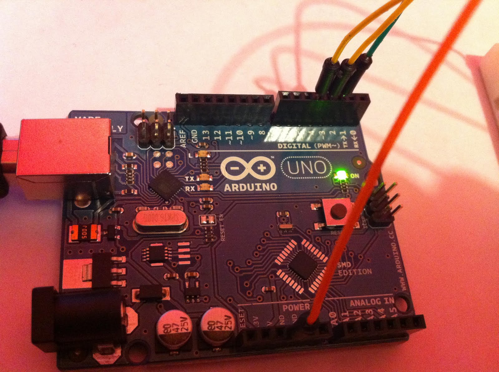
Finalmente conecte los sensores de presión a Arduino y luego use MAXDUINO para ocupar Max/Msp y al presionar el sensor suene una melodía. Falto crear una interfaz más concreta, pero tengo los sensores y programa funcionando. Es posible que el dispositivo cambie de forma y también en el contenido de la música.
Foto finales del programa funcionando:


Video: